We use cookies to make your experience better. To comply with the new e-Privacy directive, we need to ask for your consent to set the cookies. Learn more.
www.instrumentation2000.com C/O Industrial Process Measurement, Inc. 3910 Park Ave, Unit 7 Edison, NJ 08820 USA (732) 632-6400
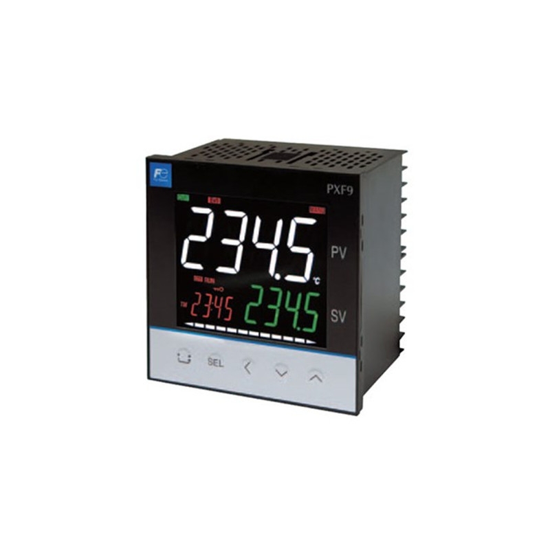
Fuji Electric PXF9 Temperature Controller
| The Fuji Electric PXF9 temperature controller is the successor to the PXR9. It is crafted with several input and output options as well as sophisticated control functions making is suitable for a wide range of uses. You can use any input among RTD, thermocouples, voltage, current, and mV. Switching the input is a simple parameter change. |
General specifications Power supply: 100 V (-15%) to 240 V (+10%) AC, 50/60 Hz; 24 V (±10%) DC/AC Power consumption: 13 VA MAX. (100 to 240 V AC), 8 VA MAX. (24 V DC/AC) Insulation resistance: 20 MΩ or more (at 500 V DC) Withstand voltage: Power source ↔ all terminals: 1500 V AC for 1 min Relay contact output ↔ all terminals: 1500 V AC for 1 min Between others 500 V AC for 1 min
Input section Process value input Number of input: 1 Input setting: Programmable scale Input signal: See Table 1 (Universal input: thermocouple, RTD, voltage, current) Standard measurement range and input type: See Table 1 Indication accuracy (at Ta = 23°C): • Thermocouple input: either ±1°C ±1 digit or ±0.3% ±1 digit of indicated value, whichever is larger *except: Thermocouple B: 0 to 400°C: no accuracy assurance Thermocouple R: 0 to 500°C: ±3°C ±1 digit Thermocouples K, T, E, U, or N: -200 to -100°C: ±2°C ±1 digit • RTD input: ±0.8°C ±1 digit or ±0.2% ±1 digit of indicated value, whichever is larger • mV input, voltage input, current input: ±0.3%FS ±1 digit Temperature effect on sensitivity: ±0.3%FS/10°C Indication resolution: See Table 1 Input sampling rate: 50 ms Input impedance: • Thermocouple, mV input: 1 MΩ or more • Current input: 150 Ω or less (built-in diode) • Voltage input: About 1 MΩ Variation by signal source resistance: • Thermocouple, mV input: ±0.3%FS ±1 digit per 100 Ω • Voltage input: ±0.3%FS ±1 digit per 500 Ω Allowable wiring resistance: RTD: 10 Ω or less (per wire) Allowable input voltage: • DC voltage input: within ±35V • Current input: within ±25 mA • Thermocouple, RTD, mV input: within ±5 V Noise reduction ratio: • Normal mode: 40 dB (50/60 Hz) • Common mode: 120 dB (50/60 Hz) • Between input and power supply: ±1°C, at 220 V AC, 50/60 Hz Input correction: (a) User adjustment: ±50%FS for each of zero and span point (b) Process value shift: ±10%FS (c) Input filter: 0.0 to 120.0 s (filter OFF if set at 0.0) (d) Square root extraction: -0.1 to 105% (OFF if set to -0.1%) Overrange, underrange: Beyond range of -5 to 105% (accuracy not guaranteed between -5 and 0, and between 100 and 105%FS) *Pt (-200 to 850°C) input: out of the range between -2 to 105% 0 to 10 V DC input: out of the range between -2 to 105% Thermocouple E input: out of the range between -5 to 102%
Remote SV input (optional) Number of inputs: 1 Input signal: Voltage: 0 to 5 V DC /1 to 5 V DC/0 to 10 V DC, Current: 0 to 20 mA DC/4 to 20 mA DC (a 250Ω resistor is required for current input) Input impedance: About 1 MΩ Sampling rate: 50 ms
Current transformer (CT) input (optional) Input type: Single phase CT, 1 point For 1 A to 30 A: CTL-6-S-H For 20 A to 100 A: CTL-12-S36-8F Range of detected current: 1 A to 100 A Detected current accuracy: Setpoint ±5% FS Detected current resolution: 0.1 A ON time necessary for detection: 300 ms MIN.
Digital input (DI) (optional) Number of points: Up to 3 Specifications: No-voltage contact or transistor input Contact capacity: 5 V DC, about 2 mA (per point) Input judgment: ON voltage: 2 V DC or lower OFF voltage: 3 V DC or higher Sampling pulse width: 50 ms MIN. Functions: Remote mode selection, SV changeover, control standby, AT startup, timer startup, alarm unlatch, program selection, start/stop/reset, PID switching (normal/reverse), etc.
Valve position feedback signal (potentiometer) input (optional) Resistance range: 100 Ω to 2.5 kΩ (three-wire) Resolution: 0.5%FS Input accuracy: ±1.0%FS Temperature effect on sensitivity: ±0.5%FS/10°C Burnout function: Not provided
Output section Control output Number of points: Up to 2 (2 points: Heating/cooling control) Type: selected among (1) to (6) below (1) Relay contact output (SPST) • Proportional cycle: 1 to 150 s • Contact structure: SPST (single pole single throw) • Contact capacity: 250 V AC/30 V DC, 3 A (resistive load) • Minimum ON/OFF current: 10 mA (5 V DC) • Mechanical life: 20 million operations MIN. (100 operations/min) • Electrical life: 100,000 operations MIN. (rated load) (2) Relay contact output (SPDT) • Proportional cycle: 1 to 150 seconds • Contact structure: SPDT (single pole double throw) • Contact capacity: 250 V AC/30 V DC, 5 A (resistive load) • Mechanial life: 50 million operations MIN. (100 operations/min) • Electrical life: 100,000 operations MIN. (rated load) (3) SSR drive output • Proportional cycle: 1 to 150 sec • ON voltage: 12 V DC (between 10.7 and 13.2V DC) • OFF voltage: 0.5 V DC or lower • Maximum current: 20 mA DC • Load resistance: 600 Ω MIN. (4) Current output (0 to 20 mA DC/4 to 20 mA DC) • Accuracy: ±5%FS • Load resistance: 500 Ω MAX. (5) Voltage output (0 to 5 V DC/1 to 5 V DC/0 to 10 V DC/2 to 10 V DC) • Accuracy: ±5%FS • Load resistance: 10 kΩ MIN. (6) Motorized valve control output • Contact structure: 2 SPST contacts without interlock circuit *SPST: Single Pole Single Throw • Contact capacity: 250 V AC/30 V DC, 3A (resistive load) • Minimum ON/OFF current: 100 mA (24 V DC) • Mechanical life: 20 million operations MIN. (100 operations/min) • Electrical life: 100,000 operations MIN. (rated load)
Alarm output (optional) Number of outputs: Relay contact output: up to 5 (shared common) up to 3 (independent common) Output specifications: Relay contact output Contact structure: SPST (single pole single throw) Contact capacity: 250 V AC/30 V DC, 1 A (resistive load) Minimum ON/OFF current: 10 mA (5 V DC) Mechanical life: 20 million operations MIN. (100 operations/min) Electrical life: 100,000 operations MIN. (rated load) Output functions: Alarm output (see “Alarm function”), main unit control mode output, program status output, control output 1 and 2, etc. Output cycle: 100 ms
Re-transmission output (optional) Number of points: 1 Type: Current/voltage output (0 to 20 mA DC/4 to 20 mA DC/0 to 5 V DC/1 to 5 V DC/ 0 to 10 V DC/2 to 10 V DC) • Guaranteed output range: 0 to 21 mA DC/0 to 10.5 V DC • Accuracy: ±0.2%FS (±5%FS at 1 mA or smaller) • Resolution: 10,000 MIN. • Load resistance: 500 Ω MAX. (current), 10 kΩ MIN. (voltage) Output cycle: 100 ms Output contents: PV, SV, DV, MV Additional function: Scaling function
Indication/setting section Display unit Type: LCD (with backlight) Indication contents: Process value indication: 11-segment, 4-digit [white] Setpoint indication: 11-segment, 4-digit [green] Screen No. indication: 7-segment, 4-digit [orange] Indication status: 42 indicator lamps Luminance setting: possible (4 steps)
Setting section Type: Sheet type keys (with emboss) Number of keys: 5 keys
Control functions Control types ON/OFF control PID control • Dual control (heating/cooling) • PID parameters determination: Auto tuning Fuzzy PID control • Dual control (heating/cooling) • PID parameters determination: Auto tuning Self tuning control PID2 control • Dual control (heating/cooling) • PID parameters determination: Auto tuning 2-degrees-of-freedom PID • PID parameters determination: Auto tuning Position proportional PID (servo) control with position feedback • Full stroke time: 30 seconds MIN.
Control parameters • Proportional band (P): 0.1 to 999.9% • Integral time (I): 0 to 3200 s Integral time control invalidated when I = 0. • Differential time (D): 0.0 to 999.9 s Differential time control invalidated when D = 0. • Control cycle: 100 to 900 ms (in 100 ms), 1 to 99 s (in seconds) • Anti-reset windup: 0 to 100% of measurement range • Hysteresis band: 50% of measurement range (at 2-position control only) • Number of SV and PID combinations: 8 combinations. Changed by any of parameter setting, digital input, communication, user function keying, zone change.
Control mode Mode type: Auto, Manual, Remote * During 2-position control in Manual mode, 2-position manual operation with MV = 100% or 0% is operated. Mode switching: • Auto↔Manual: Balanceless·bumpless • Auto/Manual → Remote: Balance·bumpless • Auto/Manual ← Remote: Balance·bumpless
Alarm function Number of alarm setting points Up to 5 points (according to the number of DOs)
Alarm type Process value (upper limit/lower limit, absolute/deviation, range), main unit error, etc. (non-excitation, delay, latch, timer function option pro-vided)
Heater current alarm function (optional) *Current detector (CT) is to be prepared separately Detectable range: 1 A to 100 A Detected current resolution: 0.1 A Setting resolution: 0.1 A Hysteresis: 0.0 A to 100.0 A
Communication function RS-485 interface (optional) Number of points: 1 point Physical specifications: EIA-485 Protocol: Modbus-RTU Communication method: Half duplex bit serial, Asynchronous communication Code type: Data length: 8 data bits. Parity: Odd, even, none. Communication rate: 9600 bps, 19200 bps, 38.4 kbps, 115.2 kbps Connection status: Up to 32 units connectable including multidrop master function Communication distance: Up to 500 m (total connect extension) Additional functions: • Cooperative operation The function in which several temperature controllers (as slave devices) can be operated by a master temperature controller. • Programless communication The function in which a temperature controller can communicate with a PLC without program. Supported PLCs: Mitsubishi PLC Q series Siemens PLC S7 series
Data backup at power failure Memory protection: Protect by non-volatile memory
Self-diagnosis Method: Program error supervision by watchdog timer
Operation and storage conditions Operating ambient temperature: -10 to 50°C Storage temperature: -20 to 60°C Operating/storage ambient humidity: 90%RH MAX. (no condensing) Warm-up time: 30 min MIN Vibration: During transportation 9.8 m/s2 (1G) or less Impact: During transportation: 294 m/s2 (30G) or less
Structure Mounting method: Panel mount External terminals: Screw terminals, M3 Case: material: • ABS, PPO • Non-combustibility grade: UL94V-0 equivalent • Color: Black Protection structure: • Panel front side: IP66, NEMA-4X equivalent (When the panel is mounted using our genuine packing. Not water-proof if mounted closely together.) • Body: IP20 equivalent (slits on top and bottom) • Terminals: IP00 equivalent. Terminal cover can be mounted optionally. Dimensions: 96 (W) × 96 (H) × 58 (D) mm Weight: approx. 220g
User customize function Program (ramp/soak) function Number of program steps: 64 steps x 1 pattern, 32 steps x 2 pattern, 16 steps x 4 pattern 8 steps x 8 pattern (1 step = 2 segments) Control option: Operation control by digital input Status output by digital output Basic functions: (1) Segment time can be set in “Hour, Minutes” or “Minutes, Seconds” (2) Guarantee soak (3) Repeat action (4) PV start (5) Delay start (6) Power restoring function Memory backup: EEPROM
User functions Pressing the user key can perform Auto/Manual change, Standby ON/OFF change, local SV/remote SV change, ramp/soak change or other functions as assigned.
Password function 3-level password function
Simple power-monitoring function and operating days alarm Simple power-monitoring function • By connecting a current transformer (to be prepared separately), electric power consumption of a heater can be displayed. (Electric power is calculated with the fixed voltage value.) • Current detector (CT) is to be prepared separately • Current detection range: 1 A to 100 A
Operating days alarm • Displays the operating days and activates alarm output (optional) when it exceeds the setpoint. • This function is useful for preventive maintenance because it let you know the appropriate time for maintenance work.
Certification UL, C-UL
EU Directive Compliance LVD (2014/35/EU) EN 61010-1 EN 61010-2-030 EMC (2014/30/EU) EN 61326-1 (Table 2) EN 55011 (Group 1 Class A) EN 61000-3-2 (Class A) EN 61000-3-3 RoHS (2011/65/EU) EN 50581
Table 1 Measurement range
* Input signal, measurement range, and set value at the time of delivery are as follows: Thermocouple K, Measurement range from 0 through 400°C, Set value 0°C. Switching the input signal among thermocouple, RTD, current, and voltage is available by key operation on the front panel. | ||||||||||||||||||||||||||||||||||||||||||||||||||||||||||||||||||||||||||||||||||||||||||||||||||||||||||||||||||||||||||||||||