We use cookies to make your experience better. To comply with the new e-Privacy directive, we need to ask for your consent to set the cookies. Learn more.
www.instrumentation2000.com C/O Industrial Process Measurement, Inc. 3910 Park Ave, Unit 7 Edison, NJ 08820 USA (732) 632-6400
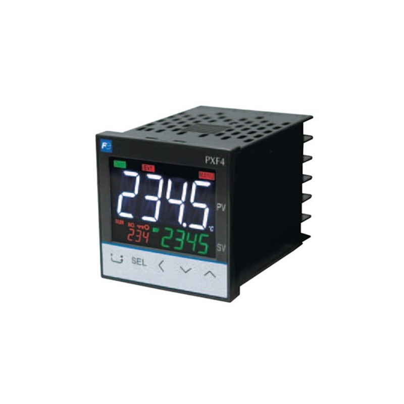
Fuji Electric PXF4 Temperature Controller
| The Fuji Electric PXF4 temperature controller was crafted as a successor to the PXR4. It is equipped with multiple input and output options as well as innovative control functions making it perfect for a large array of applications. You can use any input among RTD, thermocouples, voltage, current, and mV. Switching the input is an easy parameter change. |
General specifications Power supply: 100 V (-15%) to 240 V (+10%) AC, 50/60 Hz; 24 V (±10%) DC/AC Power consumption: 10 VA MAX. (100 to 240 V AC), 3 VA MAX. (24 V DC/AC) Insulation resistance: 20 MΩ or more (at 500 V DC) Withstand voltage: Power source ↔ all terminals: 1500 V AC for 1 min Relay contact output ↔ all terminals: 1500 V AC for 1 min Between others 500 V AC for 1 min
Input section Process value input Number of input: 1 Input setting: Programmable scale Input signal: See Table 1 (Universal input: thermocouple, RTD, voltage, current) Standard measurement range and input type: See Table 1 Indication accuracy (at Ta = 23°C): • Thermocouple input: either ±1°C ±1 digit or ±0.3% ±1 digit of indicated value, whichever is larger *except: Thermocouple B: 0 to 400°C: no accuracy assurance • RTD input: ±0.8°C ±1 digit or ±0.2% ±1 digit of indicated value, whichever is larger • mV input, voltage input, current input: ±0.3%FS ±1 digit Temperature effect on sensitivity: ±0.3%FS/10°C Indication resolution: See Table 1 Input sampling rate: 50 ms Input impedance: • Thermocouple, mV input: 1 MΩ or more • Current input: 150 Ω or less (built-in diode) • Voltage input: About 1 MΩ Variation by signal source resistance: • Thermocouple, mV input: ±0.3%FS ±1 digit per 100 Ω • Voltage input: ±0.3%FS ±1 digit per 500 Ω Allowable wiring resistance: RTD: 10 Ω or less (per wire) Allowable input voltage: • DC voltage input: within ±35V • Current input: within ±25 mA • Thermocouple, RTD, mV input: within ±5 V Noise reduction ratio: • Normal mode: 40 dB (50/60 Hz) • Common mode: 120 dB (50/60 Hz) • Between input and power supply: ±1°C at 220 V AC, 50/60 Hz Input correction: (a) User adjustment: ±50%FS for each of zero and span point (b) Process value shift: ±10%FS (c) Input filter: 0.0 to 120.0 s (filter OFF if set at 0.0) (d) Square root extraction: -0.1 to 105% (OFF if set to -0.1%) Overrange, underrange: Beyond range of -5 to 105% (accuracy not guaranteed between -5 and 0, and between 100 and 105%FS) *Pt (-200 to 850°C) input: out of the range between -2 to 105% 0 to 10 V DC input: out of the range between -2 to 105% Thermocouple E input: out of the range between -5 to 102%
Remote SV input (optional) Number of inputs: 1 Input signal: Voltage: 0 to 5 V DC /1 to 5 V DC/0 to 10 V DC, Current: 0 to 20 mA DC/4 to 20 mA DC (a 250Ω resistor is required for current input) Input impedance: About 1 MΩ Sampling rate: 50 ms
Current transformer (CT) input (optional) Input type: Single phase CT, 1 point For 1 A to 30 A: CTL-6-S-H For 20 A to 100 A: CTL-12-S36-8F Range of detected current: 1 A to 100 A Detected current accuracy: Setpoint ±5% FS Detected current resolution: 0.1 A ON time necessary for detection: 300 ms MIN.
Digital input (DI) (optional) Number of points: Up to 1 (Up to 3 digital inputs for motorized valve control version) Specifications: No-voltage contact or transistor input Contact capacity: 5 V DC, about 2 mA (per point) Input judgment: ON voltage: 2 V DC or lower OFF voltage: 3 V DC or higher Sampling pulse width: 50 ms MIN. Functions: Remote mode selection, SV changeover, control standby, AT startup, timer startup, alarm unlatch, program selec- tion, start/stop/reset, PID switching (normal/reverse), etc.
Output section Control output Number of points: Up to 2 (2 points: Heating/cooling control) Type: selected among (1) to (6) below (1) Relay contact output (SPST) • Proportional cycle: 1 to 150 sec • Contact structure: SPST (single pole single throw) • Contact capacity: 250 V AC/30 V DC, 3 A (resistive load) • Minimum ON/OFF current: 10 mA (5 V DC) • Mechanical life: 20 million operations MIN. (100 operations/min) • Electrical life: 100,000 operations MIN. (rated load) (2) Relay contact output (SPDT) • Proportional cycle: 1 to 150 seconds • Contact structure: SPDT (single pole double throw) • Contact capacity: 250 V AC/30 V DC, 5 A (resistive load) • Mechanial life: 50 million operations MIN. (100 operations/min) • Electrical life: 100,000 operations MIN. (rated load) (3) SSR drive output • Proportional cycle: 1 to 150 s • ON voltage: 12 V DC (between 10.7 and 13.2V DC) • OFF voltage: 0.5 V DC or lower • Maximum current: 20 mA DC • Load resistance: 600 Ω MIN. (4) Current output (0 to 20 mA DC/4 to 20 mA DC) • Accuracy: ±5%FS • Load resistance: 500 Ω MAX. (5) Voltage output (0 to 5 V DC/1 to 5 V DC/0 to 10 V DC/2 to 10 V DC) • Accuracy: ±5%FS • Load resistance: 10 kΩ MIN. (6) Motorized valve control output • Contact structure: 2 SPST contacts without interlock circuit *SPST: Single Pole Single Throw • Contact capacity: 250 V AC/30 V DC, 3A (resistive load) • Mechanical life: 20 million operations MIN. (100 operations/min) • Electrical life: 100,000 operations MIN. (rated load)
Alarm output (optional) Number of outputs: Relay contact output: Up to 3 (shared common) Up to 2 (independent common) Output specifications: Relay contact output Contact structure: SPST (single pole single throw) Contact capacity: 250 V AC/30 V DC, 1 A (resistive load) Minimum ON/OFF current: 10 mA (5 V DC) Mechanical life: 20 million operations MIN. (100 operations/min) Electrical life: 100,000 operations MIN. (rated load) Output functions: Alarm output (see “Alarm function”), main unit control mode output, program status output, control output 1 and 2, etc. Output cycle: 100 ms
Re-transmission output (optional) Number of points: 1 Type: Current/voltage output (0 to 20 mA DC/4 to 20 mA DC/0 to 5 V DC/1 to 5 V DC/ 0 to 10 V DC/2 to 10 V DC) • Guaranteed output range: 0 to 21.0 mA DC/0 to 10.5 V DC • Accuracy: ±0.2%FS (±5%FS at 1 mA or smaller) • Resolution: 10,000 MIN. • Load resistance: 500 Ω MAX. (current), 10 kΩ MIN. (voltage) Output cycle: 100 ms Output contents: PV, SV, DV, MV Additional function: Scaling function
Indication/setting section Display unit Type: LCD (with backlight) Indication contents: Process value indication: 11-segment, 4-digit [white] Setpoint indication: 11-segment, 4-digit [green] Screen No. indication: 7-segment, 3-digit [orange] Indication status: 23 indicator lamps Luminance setting: possible (4 steps)
Setting section Type: Sheet type keys (with emboss) Number of keys: 5 keys
Control functions Control types ON/OFF control PID control • Dual control (heating/cooling) • PID parameters determination: Auto tuning Fuzzy PID control • Dual control (heating/cooling) • PID parameters determination: Auto tuning Self tuning control PID2 control • Dual control (heating/cooling) • PID parameters determination: Auto tuning 2-degrees-of-freedom PID • PID parameters determination: Auto tuning Position proportional PID (servo) control without position feedback • Full stroke time: 30 seconds MIN.
Control parameters • Proportional band (P): 0.1 to 999.9% • Integral time (I): 0 to 3200 s Integral time control invalidated when I = 0. • Differential time (D): 0.0 to 999.9 s Differential time control invalidated when D = 0. • Control cycle: 100 to 900 ms (in 100 ms), 1 to 99 s (in seconds) • Anti-reset windup: 0 to 100% of measurement range • Hysteresis band: 50% of measurement range (at 2-position control only) • Number of SV and PID combinations: 8 combinations. Changed by any of parameter setting, digital input, communication, user function keying, zone change.
Control mode Mode type: Auto, Manual, Remote * During 2-position control in Manual mode, 2-position manual operation with MV = 100% or 0% is operated. Mode switching: • Auto↔Manual: Balanceless·bumpless • Auto/Manual → Remote: Balance·bumpless • Auto/Manual ← Remote: Balance·bumpless
Alarm function Number of alarm setting points 3 points
Alarm type Process value (upper limit/lower limit, absolute/deviation, range), main unit error, etc. (non-excitation, delay, latch, timer function option pro- vided)
Heater current alarm function (optional) *Current detector (CT) is to be prepared separately Detectable range: 1 A to 100 A Detected current resolution: 0.1 A Setting resolution: 0.1 A Hysteresis: 0.0 A to 100.0 A
Communication function 7.1 RS-485 interface (optional) Number of points: 1 point Physical specifications: EIA-485 Protocol: Modbus-RTU Communication method: Half duplex bit serial, Asynchronous communication Code type: Data length: 8 data bits. Parity: Odd, even, none. Communication rate: 9600 bps, 19200 bps, 38.4 kbps, 115.2 kbps Connection status: Up to 32 units connectable including multidrop master function Communication distance: Up to 500 m (total connect extension) Additional functions: • Cooperative operation The function in which several temperature controllers (as slave devices) can be operated by a master tem- perature controller. • Programless communication The function in which a temperature controller can com- municate with a PLC without program. Supported PLCs: Mitsubishi PLC Q series Siemens PLC S7 series
Data backup at power failure Memory protection: Protect by non-volatile memory
Self-diagnosis Method: Program error supervision by watchdog timer
Operation and storage conditions Operating ambient temperature: -10 to 50°C Storage temperature: -20 to 60°C Operating/storage ambient humidity: 90%RH MAX. (no condensing) Warm-up time: 30 min MIN Vibration: During transportation 9.8 m/s2 (1G) or less Impact: During transportation: 294 m/s2 (30G) or less
Structure Mounting method: Panel mount External terminals: Screw terminals, M3 Case: material: • ABS, PPO • Non-combustibility grade: UL94V-0 equivalent • Color: Black Protection structure: • Panel front side: IP66, NEMA-4X equivalent (When the panel is mounted using our genuine packing. Not water-proof if mounted closely together.) • Body: IP20 equivalent (slits on top and bottom) • Terminals: IP00 equivalent. Terminal cover can be mounted optionally. Dimensions: 48 (W) × 48 (H) × 58 (D) mm Weight: approx. 100g
User customize function Program (ramp/soak) function Number of program steps: 64 steps x 1 pattern, 32 steps x 2 pattern, 16 steps x 4 pattern 8 steps x 8 pattern (1 step = 2 segments) Control option: Operation control by digital input Status output by digital output Basic functions: (1) Segment time can be set in “Hour, Minutes” or “Minutes, Seconds” (2) Guarantee soak (3) Repeat action (4) PV start (5) Delay start (6) Power restoring function Memory backup: EEPROM
User functions Pressing the user key can perform Auto/Manual change, Standby ON/OFF change, local SV/remote SV change, ramp/soak change or other functions as assigned.
Password function 3-level password function
Simple power-monitoring function and operating days alarm Simple power-monitoring function • By connecting a current transformer (to be prepared separately), electric power consumption of a heater can be displayed. (Electric power is calculated with the fixed voltage value.) • Current detector (CT) is to be prepared separately • Current detection range: 1 A to 100 A
Operating days alarm • Displays the operating days and activates alarm output (optional) when it exceeds the setpoint. • This function is useful for preventive maintenance because it let you know the appropriate time for maintenance work.
Certification UL, C-UL
15. EU Directive Compliance LVD (2014/35/EU) EN 61010-1 EN 61010-2-030 EMC (2014/30/EU) EN 61326-1 (Table 2) EN 55011 (Group 1 Class A) EN 61000-3-2 (Class A) EN 61000-3-3 RoHS (2011/65/EU) EN 50581
Table 1 Measurement range
* Input signal, measurement range, and set value at the time of delivery are as follows: Thermocouple K, Measurement range from 0 through 400°C, Set value 0°C. Switching the input signal among thermocouple, RTD, current, and voltage is available by key operation on the front panel. | ||||||||||||||||||||||||||||||||||||||||||||||||||||||||||||||||||||||||||||||||||||||||||||||||||||||||||||||||||||||||||||||||