We use cookies to make your experience better. To comply with the new e-Privacy directive, we need to ask for your consent to set the cookies. Learn more.


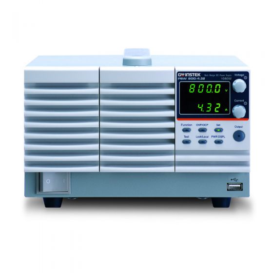
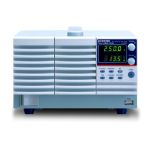
The PSW 800-4.32 is a single output programmable switching DC power supply that covers a power range up to 1080W. A very useful feature for DUT protection are the CV and CC selections. While in CV mode the power output is turned on and the voltage rises to the LED forward voltage. Then the current will peak up and exceed the preset value of current limit. To limit the current spike occurred at the threshold voltage and protect the DUT from the inrush current damage the PSW-Series is able to run under CC priority.
Another way the PSW prevents DUT damage is with the OVP and OCP protections. Both the OVP and OCP can be selected, with the default level set at 110%, of the rated voltage / current of the power supply. The PSW has available at the rear panel the LabView driver. The driver is for external control of the power On/Off and the external monitoring of the power output voltage and current.
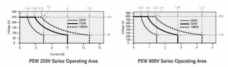
Multi-Range Operation
Model | PSW | 800-4.32 | |
Rated Output Voltage | V | 800 | |
Rated Output Current | A | 4.32 | |
Rated Output Power | W | 1080 | |
Power Ratio | -- | 3.2 | |
Constant Voltage Mode | PSW | 800-4.32 | |
Line Regulation (*1) | mV | 403 | |
Load Regulation (*2) | mV | 405 | |
Ripple and Noise (*3) | |||
| p-p (*4) | mV | 200 |
| r.m.s (*5) | mV | 30 |
Temperature coefficient | ppm/°C | 100ppm/°C of ra ted output voltage, after a 30 minute warm-up. | |
Remote sense compensation voltage | V/wire | 1 | |
Rise Time (*6) | |||
| Rated Load | ms | 150 |
| No Load | ms | 150 |
Fall Time (*7) | |||
| Rated Load | ms | 300 |
| No Load | ms | 2000 |
Transient response time (*8) | ms | 2 | |
Constant Current Mode | PSW | 800-4.32 | |
Line regulation (*1) | mA | 9.32 | |
Load regulation (*9) | mA | 9.32 | |
Ripple and noise | |||
| r.m.s (*5 ) | mA | 15 |
Temperature coefficient | ppm/°C | 200ppm/°C of rated output current, after a 30 minute warm-up . | |
Protection Function | PSW | 800-4.32 | |
Over voltage protection (OVP) | |||
| Setting range | V | 20-880 |
| Setting accuracy |
| ± (2% of rated output voltage) |
Over current protection (OCP) | |||
| Setting range | A | 0.432-4.752 |
| Setting accuracy |
| ± (2% of rated output current) |
Over temperature protection (OTP) | |||
| Operation |
| Turn the output off. |
Low AC input protection (AC-FAIL) | |||
| Operation |
| Turn the output off. |
Power limit (POWER LIMIT) | |||
| Operation |
| Over power limit. |
| Value (fixed) |
| Approx. 105% of rated output power |
Front Panel | PSW | 800-4.32 | |
Display, 4 digits | |||
| Voltage accuracy 0.1% + | mV | 400 |
| Current accuracy 0.1% + | mA | 6 |
Programming and Measurement (Interface) | PSW | 800-4.32 | |
Voltage programming accuracy 0.1% + | mV | 400 | |
Current programming accuracy 0.1% + | mA | 6 | |
Voltage programming resolution | mV | 14 | |
Current programming resolution | mA | 1 | |
Voltage measurement accuracy 0.1% + | mV | 400 | |
Current measurement accuracy 0.1% + | mA | 6 | |
Voltage measurement resolution | mV | 14 | |
Current measurement resolution | mA | 1 | |
Common Specification | |||
Input Characteristics | PSW | 800V | |
Nominal input rating |
| 100Vac to 240Vac, 50Hz to 60Hz, single phase | |
Input voltage range |
| 85Vac ~ 265Vac | |
Input voltage range |
| 47Hz ~ 63Hz | |
Maximum input current | |||
| 100Vac | A | 360W: 5A, 720W: 10A, 1080W: 15A |
| 200Vac | A | 360W: 2.5A, 720W: 5A, 1080W: 7.5A |
Inrush current | A | < 25A for 360W, < 50A for 720W, < 75A for 1080W | |
Maximum input power | VA | 360W: 500VA, 720W: 1000VA, 1080W: 1500VA | |
Power factor | |||
| 100Vac |
| 0.99 |
| 200Vac |
| 0.97 |
Efficiency | |||
| 100Vac | % | 80 |
| 200Vac | % | 82 |
Hold-up time |
| 20ms or greater | |
Analog Programming and Monitoring | PSW | 800V | |
External voltage control output voltage |
| Accuracy and linearity: ±0.5% of rated output voltage. | |
External voltage control output current |
| Accuracy and linearity: ±1% of rated output current. | |
External resistor control output voltage |
| Accuracy and linearity: ±1.5% of rated output voltage. | |
External resistor control output current |
| Accuracy and linearity: ±1.5% of rated output current. | |
Output voltage monitor | |||
| Accuracy | % | ±2 |
Output current monitor | |||
| Accuracy | % | ±2 |
Shutdown control |
| Turns the output off with a LOW (0V to 0.5V) or short-circuit. | |
Output on/off control |
| Possible logic selections: | |
CV/CC/ALM/PWR ON/OUT ON indicator |
| Photocoupler open collector output; Maximum voltage 30V, maximum sink current 8mA. | |
Series and Parallel Capability | PSW | 800V | |
Parallel number | Units | 3 | |
Series Number | Units | None | |
Front Panel | |||
Indications |
| GREEN LED's: | |
Buttons |
| Function, OVP/OCP, Set, Test, Lock/Local, PWR DSPL, Output | |
Knobs |
| Voltage, Current | |
USB port |
| Type A USB connector | |
Interface Capabilities | |||
USB |
| TypeA: Host, TypeB: Slave, Speed: 1.1/2.0, USB Class: CDC(Communications Device Class) | |
LAN |
| MAC Address, DNS IP Address, User Password, Gateway IP Address, Instrument IP Address, Subnet Mask | |
GPIB |
| Optional: GUG-001 (GPIB to USB Adapter) | |
Environmental Conditions | |||
Operating temperature |
| 0˚C to 50˚C | |
Storage temperature |
| -25˚C to 70˚C | |
Operating humidity |
| 20% to 85% RH; No condensation | |
Storage humidity |
| 90% RH or less; No condensation | |
Altitude |
| Maximum 2000m | |
General Specifications | |||
Weight (main unit only) | kg | Approx. 3kg for 360W, | |
Dimensions (WxHxD) | mm3 | 360W: 71×124×350mm, | |
Cooling |
| Forced air cooling by internal fan. | |
EMC |
| Complies with the European EMC directive 2004/108 /EC for Class A test and measurement products. | |
Safety |
| Complies with the European Low Voltage Directive 2006 /95/EC and carries the CE-marking. | |
Withstand voltage |
| Between input and chassis: No abnormalities at 1500 Vac for 1 minute. | |
Between input and output: No abnormalities at 3000 Vac for 1 minute. | |||
Between output and chassis: | |||
No abnormalities at 1500 Vdc for 1 minute for 250V, 800V models. | |||
Insulation resistance |
| Between input and chassis: 500 Vdc, 100MΩ or more | |
Between input and output: 500 Vdc, 100MΩ or more | |||
Between output and chassis: | |||
1000Vdc, 100MΩ or more for 800V models. | |||
Notes
*1: At 85 ~ 132Vac or 170 ~ 265Vac, constant load.
*2: From No-load to Full-load, constant input voltage. Measured at the sensing point in Remote Sense.
*3: Measure with JEITA RC-9131B (1:1) probe
*4: Measurement frequency bandwidth is 10Hz to 20MHz.
*5: Measurement frequency bandwidth is 5Hz to 1MHz.
*6: From 10% to 90% of rated output voltage, with rated resistive load.
*7: From 90% to 10% of rated output voltage, with rated resistive load.
*8: Time for output voltage to recover within 0.1% + 10mV of its rated output for a load change from 50 to 100% of its rated output current.
*9: For load voltage change, equal to the unit voltage rating, constant input voltage.
Write Your Own Review