We use cookies to make your experience better. To comply with the new e-Privacy directive, we need to ask for your consent to set the cookies. Learn more.


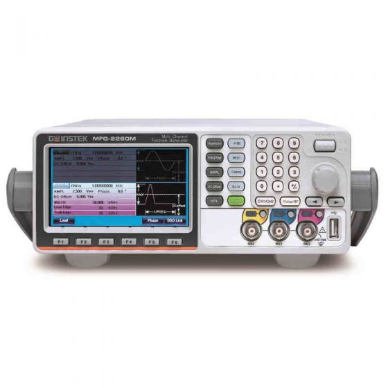
Another installment to the popular MFG-2000 series, GW Instek is introducing their MFG-2260M 60MHz Dual Channel Arbitrary Function Generator with Modulation.
See the entire GW Instek MFG-2000 series below:
GW INSTEK MFG-2000 SERIES | ||||||
| CH1 | CH2 | 25MHz Pulse Generator | RF Generator | Power Amplifier | Modulation |
Function With | Function With | |||||
●10MHZ |
| ● |
|
|
| |
●20MHZ |
| ● |
|
|
| |
●20MHZ |
| ● |
| ● | ● | |
●30MHZ |
| ● |
|
| ● | |
●60MHZ |
| ● | ●320MHZ |
| ● | |
●30MHZ | ●30MHZ | ● |
|
| ● | |
●60MHZ | ●60MHZ | ● |
|
| ● | |
●60MHZ | ●60MHZ | ● | ●320MHZ | ● | ● | |
●200MHz | ●200MHz | ● | ● | |||
CH1/ CH2 | |||||||||||||||
Arbitrary Functions |
| ||||||||||||||
| ARB function | Built-in | |||||||||||||
| Sample Rate | 200 MSa/s | |||||||||||||
| Repetition Rate | 100MHz | |||||||||||||
| Waveform Length | 16k points | |||||||||||||
| Amplitude Resolution | 14 bits | |||||||||||||
| Non-Volatile Memory | 10sets 16k points(1) | |||||||||||||
| User-defined output section | From point 2~16384 | |||||||||||||
| User-defined output marker section | From point 2 ~ 16384 | |||||||||||||
| Output mode | 1~1048575 cycles or infinite mode | |||||||||||||
Frequency Characteristics |
| ||||||||||||||
| Range | Sine | 60MHz(max) | ||||||||||||
| Square | 25MHz(max) | |||||||||||||
| Triangle, Ramp | 1MHz | |||||||||||||
| Resolution | 1μHz | |||||||||||||
| AccuracyStability | ±20 ppm | |||||||||||||
| Aging | ±1 ppm, per 1 year | |||||||||||||
| Tolerance | ≤1μHz | |||||||||||||
Output Characteristics(2) |
| ||||||||||||||
| AmplitudeRange | 1mVpp to 10 Vpp (into 50Ω) 2mVpp to 20 Vpp (open-circuit) | |||||||||||||
| Accuracy | ±2% of setting ±1 mVpp (at 1 kHz/into 50Ω without DC offset)) | |||||||||||||
| Resolution | 0.1mV or 4 digits | |||||||||||||
| Flatness | ± 1% (0.1dB) ≦1MHz ± 3% (0.3dB) ≦50 MHz ± 10% (0.9dB) ≦160MHz ± 30% (3dB) ≦320MHz (sinewave relative to 1 kHz/into 50Ω) | |||||||||||||
| Units | Vpp, Vrms, dBm | |||||||||||||
Offset | Range | ±5 Vpk ac +dc (into 50Ω) ±10Vpk ac +dc (Open circuit) | |||||||||||||
| Accuracy | 1% of setting + 5mV+ 0.5% of amplitude | |||||||||||||
Waveform Output | Impedance | 50Ω typical (fixed) > 10MΩ (output disabled) | |||||||||||||
| Protection | Short-circuit protected Overload relay automatically disables main output | |||||||||||||
| Ground Isolation | 42Vpk max | |||||||||||||
Sync Output | Range | TTL-compatible into>1kΩ | |||||||||||||
| Impedance | 50Ω standard | |||||||||||||
| Ground Isolation | 42Vpk max | |||||||||||||
Sine wave Characteristics(3) | |||||||||||||||
| Harmonic distortion | –60 dBc DC~200kHz, Ampl>0.1 Vpp –55 dBc 200kHz~1 MHz, Ampl>0.1 Vpp –45 dBc 1MHz~10 MHz, Ampl>0.1Vpp –30 dBc 10MHz~320MHz, Ampl>0.1Vpp | |||||||||||||
| Total harmonic distortion | < 0.1% (Ampl>1Vpp)DC~100 kHz | |||||||||||||
Square wave Characteristics | |||||||||||||||
| Rise/Fall Time | <15ns | |||||||||||||
| Overshoot | <5% | |||||||||||||
| Asymmetry | 1% of period +5 ns | |||||||||||||
| Variable duty Cycle | 0.01% to 99.99%(limited by the current frequency setting) | |||||||||||||
| Jitter | 20ppm+500ps(4) | |||||||||||||
Ramp Characteristics |
| ||||||||||||||
| Linearity | < 0.1% of peak output | |||||||||||||
| Variable Symmetry | 0% to 100% | |||||||||||||
Pulse Characteristics | |||||||||||||||
| Frequency | 1uHz~25MHz | |||||||||||||
| Pulse Width | ≧20nS(limited by the current frequency setting) | |||||||||||||
| Variable duty Cycle | 0.01%~99.99%(limited by the current frequency setting) | |||||||||||||
| Overshoot | <5% | |||||||||||||
| Jitter | 20ppm +500ps(4) | |||||||||||||
Pulse Generator | |||||||||||||||
Amplitude | 1mVpp to 2.5 Vpp (into 50Ω) 2mVpp to 5 Vpp (open-circuit) | ||||||||||||||
Offset | ±1 Vpk ac +dc (into 50Ω) ±2Vpk ac +dc (Open circuit) | ||||||||||||||
Frequency | 1uHz~25MHz | ||||||||||||||
Pulse Width | 20nS~999.9ks(limited by the current frequency setting) | ||||||||||||||
Variable duty Cycle | 0.01%~99.99%(limited by the current frequency setting) | ||||||||||||||
Leading and Trailing Edge Time(5) | 10nS~20S(1ns resolution) (limited by the current frequency and pulse width settings) | ||||||||||||||
Overshoot | <5% | ||||||||||||||
Jitter | 100ppm +500ps(4) | ||||||||||||||
RF Generator | |||||||||||||||
Arbitrary Functions |
| ||||||||||||||
| ARB function | Built-in | |||||||||||||
| Sample Rate | 200 MSa/s | |||||||||||||
| Repetition Rate | 100MHz | |||||||||||||
| Waveform Length | 16k points | |||||||||||||
| Amplitude Resolution | 14 bits | |||||||||||||
| User-defined output section | From point 2~16384 (optional) | |||||||||||||
| Jitter | 20ppm +5ns | |||||||||||||
Frequency Characteristics |
| ||||||||||||||
| Range | Sine |
| ||||||||||||
| Square | 25MHz(max) | |||||||||||||
| Triangle, Ramp | 1MHz | |||||||||||||
| Resolution | 1μHz | |||||||||||||
| AccuracyStability | ±20 ppm | |||||||||||||
| Aging | ±1 ppm, per 1 year | |||||||||||||
| Tolerance | ≤1μHz | |||||||||||||
Output Characteristics(2) |
| ||||||||||||||
| Amplitude(into 50Ω) | 1mVpp to 2 Vpp (MFG-2XXXMF) 1mVpp to 1 Vpp (MFG-2XXXMR) | |||||||||||||
| Accuracy | ±2% of setting ±1 mVpp (at 1 kHz/into 50Ω without DC offset)) | |||||||||||||
| Resolution | 0.1mV or 4 digits | |||||||||||||
| Flatness | ± 1% (0.1dB) ≦1MHz ± 3% (0.3dB) ≦50 MHz ± 10% (0.9dB) ≦160MHz ± 30% (3dB) ≦320MHz (sinewave relative to 1 kHz/into 50Ω) | |||||||||||||
Offset | ±1 Vpk ac +dc (into 50Ω) ±2Vpk ac +dc (Open circuit) | ||||||||||||||
Waveform Output | Impedance | 50Ω typical (fixed) > 10MΩ (output disabled) | |||||||||||||
Sine wave Characteristics(3) | |||||||||||||||
| Harmonic distortion | –60 dBc DC~200kHz, Ampl>0.1 Vpp –55 dBc 200kHz~1 MHz, Ampl>0.1 Vpp –45 dBc 1MHz~10 MHz, Ampl>0.1Vpp –30 dBc 10MHz~320MHz, Ampl>0.1Vpp | |||||||||||||
| Total harmonic distortion | < 0.1% (Ampl>1Vpp)DC~100 kHz | |||||||||||||
Square wave Characteristics | |||||||||||||||
| Rise/Fall Time | <15ns | |||||||||||||
| Overshoot | <5% | |||||||||||||
| Asymmetry | 1% of period +5 ns | |||||||||||||
| Variable duty Cycle | 0.01% to 99.99%(limited by the current frequency setting) | |||||||||||||
| Jitter | 20ppm+500ps(4) | |||||||||||||
Ramp Characteristics |
| ||||||||||||||
| Linearity | < 0.1% of peak output | |||||||||||||
| Variable Symmetry | 0% to 100% | |||||||||||||
Modulation/Sweep |
| ||||||||||||||
| Modulation Type | AM,FM,PM,FSK,PWM (The detail same as CH1 modulation specification) | |||||||||||||
| Sweep type | Frequency | |||||||||||||
| Source | INT/EXT(INT only for AM,FM,PM, PWM) | |||||||||||||
PSK |
| ||||||||||||||
| Carrier Waveforms | Sine, Square, Triangle, Ramp, Pulse | |||||||||||||
| Modulating Waveforms | 50% duty cycle square | |||||||||||||
| Internal Frequency | 2mHz to 1 MHz | |||||||||||||
| Phase Range | 0∘~360.0∘ | |||||||||||||
| Source | Internal / External | |||||||||||||
ASK |
| ||||||||||||||
| Carrier Waveforms | Sine, Square, Triangle, Ramp, Pulse | |||||||||||||
| Modulating Waveforms | 50% duty cycle square | |||||||||||||
| Internal Frequency | 2mHz to 1 MHz | |||||||||||||
| AmplitudeRange | 0%~100.0% | |||||||||||||
Source | Internal / External | ||||||||||||||
Power Amplifier | |||||||||||||||
Input Impedance | 10KΩ | ||||||||||||||
Input voltage | 1.25Vpmax | ||||||||||||||
Working Mode | Constant Voltage | ||||||||||||||
Gain | 20dB | ||||||||||||||
Output Power (RL=8Ω) | 20W(Square) | ||||||||||||||
Output Voltage | 12.5Vpmax | ||||||||||||||
Output Current | 1.6Amax | ||||||||||||||
Rise/Fall Time | <2.5uS | ||||||||||||||
Full Power Bandwidth | DC-100KHz | ||||||||||||||
Overshoot | 5% | ||||||||||||||
Total harmonic distortion | < 0.1% (Ampl>1Vpp) 20Hz~20 kHz | ||||||||||||||
Ground Isolation | 42Vpk max | ||||||||||||||
Advanced Functions | |||||||||||||||
AM Modulation | |||||||||||||||
| Carrier Waveforms | Sine, Square, Triangle, Ramp, Pulse, Arb | |||||||||||||
| Modulating Waveforms | Sine, Square, Triangle,Upramp, Dnramp | |||||||||||||
| Modulating Frequency | 2mHz to 20kHz (Int)DC to 20kHz (Ext) | |||||||||||||
| Depth | 0% to 120.0% | |||||||||||||
| Source | Internal / External | |||||||||||||
FM Modulation | |||||||||||||||
| Carrier Waveforms | Sine, Square, Triangle, Ramp | |||||||||||||
| Modulating Waveforms | Sine, Square, Triangle,Upramp, Dnramp | |||||||||||||
| Modulating Frequency | 2mHz to 20kHz (Int) DC to 20kHz (Ext) | |||||||||||||
| Peak Deviation | DC to max frequency | |||||||||||||
| Source | Internal / External | |||||||||||||
PM | |||||||||||||||
| Carrier Waveforms | Sine, Square, Triangle, Ramp | |||||||||||||
| Modulating Waveforms | Sine, Square, Triangle, Upramp, Dnramp | |||||||||||||
| Modulation Frequency | 2mHz to 20kHz (Int) DC to 20kHz (Ext) | |||||||||||||
| Phase deviation | 0∘~360.0∘ | |||||||||||||
| Source | Internal / External | |||||||||||||
SUM | |||||||||||||||
| Carrier Waveforms | Sine, Square, Triangle, Ramp | |||||||||||||
| Modulating Waveforms | Sine, Square, Triangle, Upramp, Dnramp | |||||||||||||
| Modulation Frequency | 2mHz to 20kHz (Int) DC to 20kHz (Ext) | |||||||||||||
| SUM depth | 0%~100.0% | |||||||||||||
| Source | Internal / External | |||||||||||||
PWM | |||||||||||||||
| Carrier Waveforms | Sine, Square, Triangle, Ramp | |||||||||||||
| Modulating Waveforms | Sine, Square, Triangle, Upramp, Dnramp | |||||||||||||
| Modulation Frequency | 2mHz to 20kHz (Int) DC to 20kHz (Ext) | |||||||||||||
| Phase deviation | 0%~100.0% pulse width | |||||||||||||
| Source | Internal / External | |||||||||||||
FSK | |||||||||||||||
| Carrier Waveforms | Sine, Square, Triangle, Ramp, Pulse | |||||||||||||
| Modulating Waveforms | 50% duty cycle square | |||||||||||||
| Internal Frequency | 2mHz to 1 MHz | |||||||||||||
| FrequencyRange | 1μHz to max frequency | |||||||||||||
| Source | Internal / External | |||||||||||||
Sweep | |||||||||||||||
| Waveforms | Sine, Square, Triangle, Ramp | |||||||||||||
| Type | Linear or Logarithmic | |||||||||||||
| Sweep direction | Sweep up or sweep down | |||||||||||||
| Start/Stop Freq | 1uHz to max frquency | |||||||||||||
| Sweep Time | 1ms to 500s | |||||||||||||
| Source | Internal / External | |||||||||||||
| Trigger | Single, External, Internal. | |||||||||||||
| Marker | Marker signal on falling edge(programmable) | |||||||||||||
| Source | Internal / External | |||||||||||||
Burst | |||||||||||||||
| Waveforms | Sine, Square, Triangle, Ramp | |||||||||||||
| Frequency | 1uHz~Max Frequency | |||||||||||||
| Pulse count | 1~1000000 Cycles or intfinite | |||||||||||||
| Start/ Stop Phase | -360.0∘~+360.0∘ | |||||||||||||
| Internal Frequency | 1 us~500 s | |||||||||||||
| Gate source | External Trigger | |||||||||||||
| Trigger Source | Single, External, Internal. | |||||||||||||
Trigger Delay | NCycle, Infinite | 0s~100 s | |||||||||||||
External Trigger Input |
| ||||||||||||||
| Type | For FSK, Burst, Sweep | |||||||||||||
| Input Level | TTL Compatibility | |||||||||||||
| Slope | Rising or Falling(Selectable) | |||||||||||||
| Pulse Width | >100ns | |||||||||||||
| Input Impedance | 10kΩ,DC coupled | |||||||||||||
External Modulation Input |
| ||||||||||||||
| Type | For AM, FM, PM,SUM,PWM | |||||||||||||
| Voltage Range | ±5V full scale | |||||||||||||
| Input Impedance | 10kΩ | |||||||||||||
| Frequency | DC to 20kHz | |||||||||||||
| Ground Isolation | 42Vpk max | |||||||||||||
Trigger Output |
| ||||||||||||||
| Type | For FSK,Burst, Sweep | |||||||||||||
| Level | TTL Compatible into 50Ω | |||||||||||||
| Pulse Width | >450ns | |||||||||||||
| Maximum Rate | 1MHz | |||||||||||||
| Fan-out | ≥4 TTL Load | |||||||||||||
| Impedance | 50Ω Typical | |||||||||||||
Frequency Counter | |||||||||||||||
| Range | 5Hz to 150MHz | |||||||||||||
| Accuracy | Time Base accuracy±1count | |||||||||||||
| Time Base | ±20ppm (23˚C ±5˚C) | |||||||||||||
| Resolution | The maximum resolution is: 100nHz for 1Hz, 0.1Hz for 100MHz. | |||||||||||||
Input Impedance | 1kΩ/1pf | ||||||||||||||
Sensitivity | 35mVrms ~ 30Vms (5Hz to 150MHz) | ||||||||||||||
Ground Isolation | 42Vpk max | ||||||||||||||
Dual Channel Function(CH1/CH2) | |||||||||||||||
Phase | -180∘ ~180∘ | ||||||||||||||
Synchronize phase | |||||||||||||||
Track | CH2=CH1 | ||||||||||||||
Coupling | Frequency(Ratio or Difference) | ||||||||||||||
Amplitude & DC Offset | |||||||||||||||
Dsolink | √ | ||||||||||||||
Save/Recall | 10 Groups of Setting Memories | ||||||||||||||
Interface | LAN(MFG 22XX Series only), USB | ||||||||||||||
Display | 4.3’’ TFT LCD 480 × 3 (RGB) × 272 | ||||||||||||||
General Specifications | |||||||||||||||
Power Source | AC100~240V, 50~60Hz or AC100~120V, AC220~240V, 50~60Hz | ||||||||||||||
Power Consumption | 30W or 80W(With power amplifier) | ||||||||||||||
Operating Environment | Temperature to satisfy the specification : 18 ~ 28˚C Operating temperature : 0 ~ 40˚C Relative Humidity: ≤ 80%, 0 ~ 40˚C ≤ 70%, 35 ~ 40˚C Installation category: CAT II | ||||||||||||||
Operating Altitude | 2000 Meters | ||||||||||||||
Pollution Degree | IEC 61010 degree 2, Indoor use | ||||||||||||||
Storage Temperature | -10~70˚C, Humidity: ≤70% | ||||||||||||||
Dimensions (WxHxD) | 266(W) x 107(H) x 293(D) mm | ||||||||||||||
Weight | Approx. 2.5kg | ||||||||||||||
Safety designed to | EN61010-1 | ||||||||||||||
Accessories | GTL-101× 1(MFG-21XX) GTL-101× 2(MFG-22XX) | ||||||||||||||
Quick Start Guide ×1 | |||||||||||||||
(1). A total of ten waveforms can be stored. (Every waveform can be composed of a maximum of 16k points.)
(2). Add 1/10th of output amplitude and offset specification per ºC for operation outside of 0ºC to 28ºC range (1-year specification).
(3). DC offset set to zero,
(4). Jitter specification for RF Generator: 20ppm +5ns.
(5). Only Pulse channel support
Write Your Own Review
- Educational Institutions
- Automotive Electronics