We use cookies to make your experience better. To comply with the new e-Privacy directive, we need to ask for your consent to set the cookies. Learn more.


The Fuji Electric FSV ultrasonic flow meter is the latest generation of top performance ultrasonic liquid flow meters using transit time technology. It is particularly efficient in applications where high accuracy is required and the flow meter needs to be installed without shutting down the process. It is the ideal option for measuring flow rates of relatively clean, homogeneous liquids in closed, filled pipes.
The FSV uses advanced digital signal processing technology to provide a compact, lightweight solution with accuracies that are better than ±1% of flow rate with minimal influence by the pressure or temperature of the measured fluid. It offers best-in-class anti-bubble performance, which allows for precision readings with air bubble content as high as 12% volume at 3ft/s velocity.
The durable construction makes it perfect for installation in internal and external environments where IP66 (NEMA 4X) protection is required and it is 2/3 the size of its predecessor, the Time Delta-S.
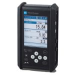
Configuration is easy and intuitive via push buttons on the front panel. Alternatively, free PC compatible software is available, allowing multiple configurations to be stored and downloaded from a PC to the meter. Real-time trending and data logging as well as diagnostics can be performed with the loader software. The software also includes a sensor spacing calculation tool. A selection of outputs which include 4-20mA, transistor outputs, and RS485 (Modbus) are available for when flow rates and totals need to be transmitted.
The FSV requires clamp-on sensors. These sensors clamp to the outside of pipes and cover pipe diameters from 13 to 6000mm (0.5 to 235 inches) at liquid temperatures from -40 to 200°C (-40 to 390°F). The system requires a straight pipe run of 10x and 5x pipe diameters upstream and downstream respectively.
Transducer Options
| FSSD1 Transducer | 12.6 inch rail for 0.5 to 4 inch pipes, -40 to 212°F, 2MHz, includes mounting straps and silicone grease. | |
| FSSC Transducer | 21.26 inch rail for 2 to 48 inch pipes, -40 to 248°F, 1MHz, includes mounting straps and silicone grease. | |
| FSSE Transducer | 8 to 235 inch pipes, -40 to 175°F, 0.5MHz, includes 4in BNC cable for connecting to Portaflow-C. | |
| FSSH Transducer | 19 inch rail for 2 to 16 inch pipes, -40 to 390°F, 2MHz, includes mounting straps and silicone grease. |
| Operational specifications |
| System configuration: |
| Single-path system of a flow transmitter (Model FSV) and a detector (Model FSS) |
| Applicable detector: |
| FSSA (2MHz), FSSC (1MHz) |
| Applicable fluid: |
| Homogenous liquid where the ultrasonic signal can be transmitted Bubble quantity: 0 to 12vol% (for pipe size 50A, water, velocity 1m/s) Fluid turbidity: 10000mg/L max. Type of flow: Fully-developed turbulent or laminar flow in a full-filled pipe |
| Flow velocity range: |
| 0 to ±0.3 ... ±32m/s |
| Power supply: 100 to 240V AC +10%/-15%, 50/60Hz; or 20 to 30V DC |
| Signal cable (between detector and converter): |
| Coaxial cable (150m max.) applicable up to 300m depending on the condition. Heat resistance: 80°C |
| Installation environment: |
| Non-explosive area without direct sunlight, corrosive gas and heat radiation. |
| Ambient temperature: |
| Flow transmitter: -20 to +55°C Detector: -20 to +60°C |
| Ambient humidity: |
| Flow transmitter: 95%RH max. Detector: 90%RH max. |
| Grounding: Class D (100 Ω) |
| Arrester: Provided as standard at power supply |
Applicable piping and fluid temperature: <table 1>
| Detector | Pipe size (Inner diameter) ø mm | Applicable pipe material (Note1) | How to mount | Flued temperatur range (°C) (Note2, 3) |
| FSSA | 25 to 50 | Plastic (PVC, Others) | V method | -20 to +100 |
| 50 to 225 | Plastic (PVC, Others) Metal pipe (Stainless steel, Carbon steel, Copper, Aluminum, Others) | |||
| FSSC | 50 to 600 | V method | -40 to +120 | |
| 200 to 1200 | Z method |
Note1) Please select the FSSC type if following condition.
• When pipe material is PP or PVDF, limit of pipe wall thickness is 15mm or more for PP, 9mm or more for PVDF
• When pipe material is hard to penetrate the ultrasonic wave such as cast-iron pipe, lining pipe and old carbon steel pipe etc..,
• Llining material is tar epoxy, mortar and rubber etc..
• In case lining is removed from the pipe, Measurement can not be conducted
Note2) When silicon grease is used as acoustic coupler, Fluid temperature limit is 0 to 60°C no matter what detector is selected.
Note3) Heat-resistant shock temperature: for 30 minutes at 150°C
Note4) Please refer to the item 9 for the specification of the special detector (for small diameter pipe,large diameter pipe and high temperature)
Note5) For pipes with a diameter of 300 mm or larger, we recommend to use FSSE and mount it by Z method.
Performance specifications
| Rated accuracy: <table 2> | ||||
| Detector Type | Pipe size (diameter) mm | Flow velocity (m/s) | Accuracy | |
| Plastic pipe | Metal pipe | |||
| FSSA | ø25 to ø50 | 2 to 32 | ±2.0% of rate | – |
| 0 to 2 | ±0.04m/s | – | ||
| ø50 to ø225 | 2 to 32 | ±1.0% of rate | ±2.0% of rate | |
| 0 to 2 | ±0.02m/s | ±0.04m/s | ||
| FSSC | ø50 to ø200 | 2 to 32 | ±1.5% of rate | |
| 0 to 2 | ±0.03m/s | |||
| ø200 to ø1200 | 2 to 32 | ±1.0% of rate | ||
| 0 to 2 | ±0.02m/s | |||
Note1) Please refer to the item 9 for the specification of the special detector (for small diameter pipe, large diameter pipe and high temperature)
| Response time: | 1s (standard mode) 0.2s as selected (quick response mode) |
| Power consumption: | 15VA max. (AC power supply) 6W max. (DC power supply) |
Functional specifications
| Analog signal: | 4 to 20mA DC (1 point) Load resistance: 600Ω max. |
| Digital output: | Forward total, reverse total, alarm, acting range, flow switch, total switch assignable arbitrarily Transistor contact (isolated, open collector) • Outputs: 2 points • Normal: ON/OFF selectable • Contact capacity: 30V DC, 50mA • Output frequency: 1000P/s max. (pulse width: 5, 10, 50, 100, 200, 500, 1000ms) |
| Serial communication (option): | RS-485 (MODBUS), isolated, arrester incorporated Connectable quantity: 31 units Baud rate: 9600, 19200, 38400bps Parity: None/Odd/Even selectable Stop bits: 1 or 2 bits selectable Cable length: 1km max. Data: Flow velocity, flow rate, forward total, reverse total, status, etc. |
| Display device: | 2-color LED (Normal: green, Extraordinary: red) LCD with 2 lines of 16 characters and back light |
| Indication language: | Japanese (Katakana)/English/French/ German/Spanish (changeable) |
| Flow velocity/flow rate indication: | Instantaneous flow velocity, instantaneous flow rate indication (minus indication for reverse flow) Numerals: 8 digits (decimal point is counted as 1 digit) Unit: Metric/Inch system selectable |
| Metric system | Inch system | |
| Velocity | m/s | ft/s |
| Flow rate | L/s, L/min, L/h, L/d, kL/d, ML/d, m3/s, m3/min, m3/d, km3/d, Mm3/d, BBL/s, BBL/min, BBL/h, BBL/d, kBBL/d, MBBL/d | gal/s, gal/min, gal/h, gal/d, kgal/d, Mgal/d, ft3/s, ft3/ min, ft3/d, Kft3/d, Mft3/d, BBL/s, BBL/min, BBL/h, BBL/d, kBBL/d, MBBL/d |
Note: The ”gal” means USgal.
Total indication: Forward or reverse total value indication
(negative indication for reverse direction)
Numerals: 8 digits (decimal point is counted as 1 digit)
Unit: Metric/Inch system selectable
| Metric system | Inch system | |
| Total | mL, L, m3, km3, Mm3, mBBL, BBL, KBBL | gal, kgal, ft3, kft3, Mft3, mBBL, BBL, kBBL, ACRE-ft |
| Configuration: | Fully configurable from the 4-key pad (ESC,  ENT) ENT) |
| Zero adjustment: | Set zero/Clear available |
| Damping: | 0 to 100s (every 0.1s) for analog output and flow velocity/flow rate indication |
| Low flow rate cutoff: | 0 to 5m/s in terms of flow velocity |
| Alarm: | Digital output available for Hardware fault or Process fault |
| Burnout: | Analog output: Hold/Overscale/Underscale/ Zero selectable Flow rate total: Hold/Count selectable Burnout timer: 0 to 100s (every 1s) |
| Bi-directional range: | Forward and reverse ranges configurable independently. Hysteresis: 0 to 10% of working range Working range applicable to digital output |
| Auto-2 range: | 2 forward ranges configurable independently Hysteresis: 0 to 10% of working range Working range applicable to digital output |
| Flow switch: | Lower limit, upper limit configurable independently Digital output available for status at actuated point |
| Total switch: | Forward total switching point configurable Digital output available when actuated |
| External total preset: | Preset total settable upon contact input setting |
| Backup of power failure: | backup by non-volatile memory |
Physical specifications
| Type of enclosure: | Flow transmitter: FSV···S: IP66 FSV···H: IP67 (With large LCD) Detector: FSSA, FSSC: IP65 (When waterproot BNC connector is provided) FSSA,FSSC: IP65 (When water-proof type connector is fitting) FSSC (waterproofing): IP68 (submerged resistant structure for 5days) |
| Mounting method: | Flow transmitter: Mounted on wall or by 2B pipe Detector: Clamped on pipe surface |
| Acoustic coupler: | Acoustic coupler is a filling between detector and pipe. |
| Type of acoustic coupler: | <table 3> | |||
| Type | Silicone rubber (KE-348W) | Silicone grease (G40M) | Silicone-free grease (HIGH Z) | Grease for high temperature (KS62M) |
| Fluid temperature | -40 to +150°C | -30 to +150°C | 0 to +60°C | -30 to +250°C |
| Teflon piping | X | Ο | Ο | Ο |
In case of Teflon piping, use grease.
| Material: | Flow transmitter: Aluminum alloy | |
| Detector: | <table 4> | |
| Detector Type | Sensor housing | Guide rail |
| FSSA | PBT | SUS304 |
| FSSC | PBT | Aluminum alloy |
* Please refer to the item 9 for the specification of the special detector
(for small diameter pipe, large diameter pipe and high temperature)
| Signal cable: | • Structure: Heat-resisting high-frequency coaxial cable • Sheath: Flame-resisting PVC • Outer diameter: ø7.3mm |
| Terminal treatment | <table 5> |
| Cable type | FLYD |
| Applicable detector | FSSA, FSSC |
| Terminal of flow transmitter side | Rod terminal ×2 Amplifier terminal (M3) ×1 |
| Terminal of detector side | BNC connector × 1 Amplifier terminal (M4) ×1 |
* Please refer to the item 9 for the specification of the special detector
(for small diameter pipe, large diameter pipe and high temperature)
| Dimension, Mass: | <table 6> | ||
| Type | Dimensions | Mass.(kg) | |
| Flow transmitter | FSV···S (IP66) FSV···H (IP67) | H170 × W142 × D70mm H277 × W244 × D96mm | 1.5 4.5 |
| Detctor | FSSA FSSC | H50 × W348 × D34mm H88 × W480 × D53mm | 0.4 1 |
| Signal cable | FLYD | ø7.3mm | 90g/m |
* Please refer to the item 9 for the specification of the special detector
(for small diameter pipe, large diameter pipe and high temperature)
External terminal of flow transmitter:
plug terminal
| EU Directive Compliance |
| LVD (2014/35/EU) |
| EN 61010-1 |
| EMC (2014/30/EU) |
| EN 61326-1 (Table 2) EN 55011 (Group 1 Class A) EN 61000-3-2 (Class A) EN 61000-3-3 EN 61326-2-3 |
| RoHS (2011/65/EU) |
| EN 50581 |
Write Your Own Review
- • Boiler Feedwater
- • Building Automation Systems
- • Clean Water
- • Corrosives
- • DI/RO Water
- • Food / Beverage
- • Indoor Growing
- • Irrigation
- • NSF/ANSI 61: Drinking Water System Components
- • Pharmaceutical
- • Waste-water and Grey Water