We use cookies to make your experience better. To comply with the new e-Privacy directive, we need to ask for your consent to set the cookies. Learn more.


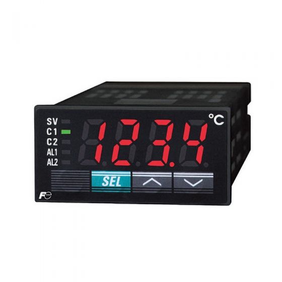
The Fuji PXR3 temperature controller is an innovative, 1/32 DIN temperature and process controller. Made for a vast range of applications, the PXR3 not only includes auto-tuning and fuzzy control, but also features self-tuning - an innovation in the control field. Self-tuning automatically re-tunes the controller under certain conditions, without the need to revert to auto-tuning.
The PXR3 accepts process and temperature inputs and extends a choice of three kinds of outputs to meet a large variety of needs in the process industries. Single or dual outputs include relay, SSR driver, or 4-20mA. The controller's standard 8-segment ramp/soak feature has been expanded to include two patterns that can be linked to create a 16-step profile.
One of the most impressive features of the PXR3 is the expansive LED display. The faceplate, designed for NEMA 4X (IP66 equivalent) is watertight and corrosion-resistant. The easy-to-use 3-button keypad makes programming fast and simple. The screw-terminal on the back further lessens the cost by eliminating the need for sockets.
Remote monitoring of up to 31 PXR series controllers at a time is possible with the RS485 option that uses the industry-standard Modbus protocol. The communications option comes with free Windows-based software, PXR-LITE. The software allows you to program PXR series controllers from the PC and view real-time data and trend graph while logging the data on to a text file.
A powerful tool for the OEM customer is the Program Loader option with Windows-based software. Programs for different applications can be saved to and from Fuji temperature PXR series controllers.
General specifications
Power supply voltage | 100 V (-15%) to 240 V (+10%) AC, 50/60 Hz or 24 V (±10%) AC, 50/60 Hz, 24 V (±10%) DC |
Power consumption | ≤ 6 VA (100 V AC) ≤ 8 VA (240 V AC, 24 V AC, 24 V DC) |
Insulation resistance | ≥ 20 MΩ (500 V DC) |
Dielectric strength | Power supply↔Ground: 1500 V AC for 1 min Power supply↔Others: 1500 V AC for 1 min Ground↔Relay output: 1500 V AC for 1 min Ground↔Alarm output: 1500 V AC for 1 min Others: 500 V AC for 1 min |
Input impedance | Thermocouple: 1 MΩ or more Voltage: 450 kΩ or more Current: 250 Ω (external resistor) |
Allowable signal source resistance | Thermocouple: 100 Ω or less Voltage: 1 kΩ or less |
Allowable wiring resistance | RTD: 10 Ω or less per wire |
Reference junction compensation accuracy | ±1ºC (at 23ºC) |
Input value correction | ±10% of measuring range |
Input filter | 0 to 900.0 s Configurable in 0.5 s steps (first order lag filter) |
Noise reduction ratio | Normal mode noise (50/60 Hz): 50 dB or more Common mode noise (50/60 Hz): 140 dB or more |
Control functions of standard type
Control action | PID control (with auto tuning, self-tuning) Fuzzy control (with auto tuning) |
Proportional band (P) | 0 to 999.9% of measuring range Configurable in 0.1% steps |
Integral time (I) | 0 to 3200 s Configurable in 1 s steps |
Differential time (D) | 0 to 999.9 s Configurable in 0.1 s steps |
On/off action if P = 0. Proportional action when I, D = 0. | |
Proportional cycle | 1 to 150 s Configurable in 1 s steps Only for relay contact output or SSR/SSC drive output |
Hysteresis width | 0 to 50% of measuring range For on/off action only |
Anti-reset windup | 0 to 100% of measuring range Automatically adjusted by auto tuning |
Input sampling cycle | 0.5 s |
Control cycle | 0.5 s |
| |
Input section | |
Input signal | Thermocouple : J, K, R, B, S, T, E, N, PLII Resistance bulb : Pt100 Voltage, current: 1 to 5 V DC, 4 to 20 mA DC (For the current input, add a provided 250 Ω resistor to the input terminal.) |
Measuring range | See Table 1. |
Burnout | For thermocouple or RTD input, a user can select either the upper limit or lower limit as the value which the control output should transmit when a burnout occurs. |
Output section of standard type (Control output 1)
| Control output 1 | Select one from the followings: • Relay contact: SPST contact: 220 V AC/30 V DC, 3A (resistive load) Mechanical life: 10 million operations (no load) Electrical life: 100,000 operations (rated load) Minimum switching current: 10 mA (5 V DC) • Voltage pulse (for SSR / SSC drive): ON: 15 V DC (12 to 16 V DC) OFF: 0.5 V DC or less Max. current: 20 mA or less • 4 to 20 mA DC: Allowable load resistance: 100 to 500 Ω |
Control functions of heating/cooling control type
(option)
Heating side proportional band (P) | 0 to 999.9 % of measuring range |
Cooling side proportional band (P) | Heating side "P" × cooling side coefficient (Automatically set in auto tuning) Cooling side proportional band coefficient: 0 to 100.0 On/off action if P = 0 |
Integral time (I) | 0 to 3200 s (common to heating and cooling sides) |
Differential time (D) | 0 to 999.9 s (common to heating and cooling sides) |
P, I, D = 0: ON/OFF action (without dead band) for heating and cooling I, D = 0: Proportional action | |
Proportional cycle | 1 to 150 s For relay contact output or SSR/SSC drive output only |
Hysteresis width | 0.5% of measuring range, common to heating and cooling sides, for on/off action only |
Anti-reset windup | 0 to 100% of measuring range Automatically adjusted by auto tuning |
Overlap, dead band | ±50% of heating side proportional band |
Input sampling cycle | 0.5 s |
Control cycle | 0.5 s |
Output section of heating/cooling control type
(control output 2) (option)
| Control output 2 | Select one from the followings: • Relay contact: SPST contact: 220 V AC/30 V DC, 3 A (resistive load) Mechanical life: 10 million operations (no load) Electrical life: 100,000 operations (rated load) Minimum switching current: 10 mA (5 V DC) • Voltage pulse (for SSR/SSC drive): ON: 15 V DC (12 to 16 V DC) OFF: 0.5 V DC or less Max. current: 20 mA or less • 4 to 20 mA DC: Allowable load resistance: 100 to 500 Ω |
Operation and display section
Parameter setting | Digital setting by 3 keys With key lock function |
Display | 4-digit, 7-segment LED (red) Process value and set value switchable |
Status indicator | Control output or alarm output |
Setting accuracy | 0.1% or less of measuring range |
Indication accuracy (at 23ºC) | Thermocouple: ± (0.5% of measuring range) ±1 digit ±1ºC Except: Thermocouple R at 0 to 500ºC: ± (1% of measuring range) ±1 digit ±1ºC Thermocouple B at 0 to 400ºC: ± (5% of measuring range) ±1 digit ±1ºC RTD, voltage, current: ± (0.5% of measuring range) ±1 digit |
Alarm (option)
Alarm kind | Absolute alarm, deviation alarm, zone alarm with upper and lower limits for each Hold (see below explanation) and latch function available |
Alarm ON-delay | 0 to 9999 s Configurable in 1 s steps |
Process alarm output | Relay contact: SPST contact: 220 V AC / 30 V DC, 1 A (resistive load) Mechanical life: 10 million operations (no load) Electrical life: 100,000 operations (rated load) Minimum switching current: 10 mA (5 V DC). MAX 2 points Output cycle: 0.5 s |
What is alarm with hold?
The alarm is not turned ON immediately even when the mesaured value is in the alarm band. It turns ON when it goes out the alarm band and enters again.
Digital input (option)
Number of points | 1 or 2 |
Contact capacity | 5 V DC, approx. 2 mA ON judgment for 2 V DC or less OFF judgment for 3 V DC or more |
Input pulse width | Minimum 0.5 s |
Available function (select one) | Set value (front SV, SV1, SV2, or SV3, switchable) Control action start/stop Ramp soak action start/reset Auto tuning start/stop Alarm latch cancel Built-in timer start |
Timer (option)
Startup | By digital input |
Setting | 0 to 9999 s Configurable in 1 s steps Default setting is 0 s. |
Action | Event ON-delay or OFF-delay |
Signal output | Uses alarm output relay. Up to 2 points available |
Communication (option)
Physical specifications | EIA RS485 |
Protocol | Modbus® RTU mode or PXR protocol (Z-ASCII) |
Communication method | 2 wires, half duplex bit serial, start-stop synchronization |
Data type | 8 bits. Parity: odd/even/none. |
Baud rate | 9600 bps |
Network topology | Multi-drop network Up to 32 controllers connectable including master station |
Communication distance | Up to 500 m |
Recommended RS232C–RS485 converter | Isolated type K3SC-10 by OMRON Co., Ltd (Japan) |
Re-transmission output (option)
Output signal | 4–20 mA DC |
Load resistance | 500 Ω or less |
Output updating | 500 ms |
Output accuracy | ±0.3% FS (at 23ºC) |
Resolution | 2000 or more |
Kind of output signal | PV, SV, DV, or MV (selectable by parameter) |
Other functions
Parameter mask | User can switch show and hide of parameters |
Ramp soak | 2 pattern × 4 steps, or 1 pattern × 8 steps Digital input allows starting or resetting the action. |
Memory backup at power outage
| Medium | Non-volatile memory |
Self-diagnosis
| Method | Program error monitoring by watchdog timer |
Operation and storage conditions
Ambient operating temperature | -10ºC to 50ºC |
Ambient operating humidity | ≤ 90% RH (no condensation) |
Storage temperature | -20ºC to 60ºC |
Structure
Mounting method | Panel mount Rail or wall mount is available by using the optional DIN rail mounting adapter |
External terminal | Rod terminal |
Case material | Plastic (flameproof grade UL94 V-0 equivalent) |
Dimensions | 24 × 48 × 98 mm |
Weight | Approx. 150 g |
Protective structure | Front panel: NEMA 4X watertight (IEC IP66 equivalent) when mounted on panel with our genuine packing. Waterproof feature is unavailable in close mounting of multiple units. Rear case: IEC IP20 |
Color | Black (front frame, case) |
Certification
UL, C-UL
EU Directive Compliance ![]()
| LVD (2014/35/EU) EN 61010-1 EN 61010-2-030 |
| EMC (2014/30/EU) EN 61326-1 (Table 2) EN 55011 (Group 1 Class A) EN 61000-3-2 (Class A) EN 61000-3-3 |
| RoHS (2011/65/EU) EN 50581 |
Table 1 Measuring range
Group |
Input signal | Range | ||
ºC | ºF | |||
I | RTD | Pt100 | -150 to 850 | -238 to 1562 |
Thermocouple | J | 0 to 800 | 32 to 1472 | |
K | 0 to 1200 | 32 to 2192 | ||
R | 0 to 1600 | 32 to 2912 | ||
B | 0 to 1800 | 32 to 3272 | ||
S | 0 to 1600 | 32 to 2912 | ||
T | -150 to 400 | -238 to 752 | ||
E | -150 to 800 | -238 to 1472 | ||
N | 0 to 1300 | 32 to 2372 | ||
PL-II | 0 to 1300 | 32 to 2372 | ||
II | 1–5 V DC | Scaling range (-1999 to 9999) | ||
4–20 mA DC | ||||
Notes:
1. For 4–20 mA DC input, add a 250-ohm resistor provided with the controller.
2. You cannot switch the input type across the groups.
3. When the measuring range is beyond 1000ºC, the decimal point is not indicated.
Write Your Own Review
- • Brewing & Fermentation
- • Cryogenics
- • Kiln
- • Refrigeration Control / Monitoring