We use cookies to make your experience better. To comply with the new e-Privacy directive, we need to ask for your consent to set the cookies. Learn more.


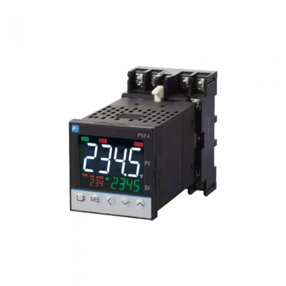
The Fuji Electric PXF4 temperature controller socket-type was designed as a successor to the PXR4 socket-type. It is geared with multiple input and output options as well as sophisticated control functions making it ideal for a wide range of applications. You can use any input among RTD, thermocouples, voltage, current, and mV. Switching the input is an easy parameter change. The socket terminal on the back makes this unit conveniently plug and play.
General specifications
| Power supply: | 100 V (-15%) to 240 V (+10%) AC, 50/60 Hz; 24 V (±10%) DC/AC |
| Power consumption: | 10 VA MAX. (100 to 240 V AC), 5 VA MAX. (24 V DC/AC) |
| Insulation resistance: | 20 MΩ or more (at 500 V DC) |
| Withstand voltage: | Power source ↔ all terminals: 1500 V AC for 1 min Relay contact output ↔ all terminals: 1500 V AC for 1 min Between others 500 V AC for 1 min |
Input section
| Process value input | |
| Number of input: | 1 |
| Input setting: | Programmable scale |
| Input signal: | See Table 1 (Universal input: thermocouple, RTD, voltage, current) |
| Standard measurement range and input type: | See Table 1 |
| Indication accuracy (at Ta = 23°C): | • Thermocouple input: ±0.5%FS ±1 digit ±1°C *Exceptions: Thermocouple B: 0 to 400°C: no accuracy assurance Thermocouple R: 0 to 500°C: ±1%FS ±1 digit ±1°C Thermocouples: -200 to -100°C: ±2°C ±1 digit • RTD input: ±0.8°C ±1 digit or ±0.2% ±1 digit of indicated value, whichever is larger • mV input, voltage input, current input: ±0.3%FS ±1 digit * Note that the sensor should be sufficiently warmed up to secure the accuracy |
| Temperature effect on sensitivity: | ±0.3%FS/10°C |
| Indication resolution: | See Table 1 |
| Input sampling rate: | 50 ms |
| Input impedance: | • Thermocouple, mV input: 1 MΩ or more • Current input: 150 Ω or less (built-in diode) • Voltage input: About 1 MΩ |
| Variation by signal source resistance: | • Thermocouple, mV input: ±0.3%FS ±1 digit per 100 Ω • Voltage input: ±0.3%FS ±1 digit per 500 Ω |
| Allowable wiring resistance: | RTD: 10 Ω or less (per wire) |
| Allowable input voltage: | • DC voltage input: within ±35V • Current input: within ±25 mA • Thermocouple, RTD, mV input: within ±5 V |
| Noise reduction ratio: | • Normal mode: 40 dB (50/60 Hz) • Common mode: 120 dB (50/60 Hz) • Between input and power supply: ±1°C at 220 V AC, 50/60 Hz |
| Input correction: | (a) User adjustment: ±50%FS for each of zero and span point (b) Process value shift: ±10%FS (c) Input filter: 0.0 to 120.0 s (filter OFF if set at 0.0) (d) Square root extraction: -0.1 to 105% (OFF if set to -0.1%) |
| Overrange, underrange: | Out of the range between -5% and 105% FS (accuracy not guaranteed between -5 and 0, and between 100 and 105% FS) *Exceptions: • JPt, Pt, 0–10 V DC: out of the range between -2% and 105% FS • Thermocouple E: out of the range between -5% and 102% FS |
Output section
| Control output | |
| Number of points: | 1 |
| Type: | |
| selected among (1) to (3) below (1) Relay contact output (SPDT) • Proportional cycle: 1 to 150 seconds • Contact structure: SPDT (single pole double throw) • Contact capacity: 250 V AC/30 V DC, 5 A (resistive load) • Mechanial life: 50 million operations MIN. (100 operations/min) • Electrical life: 100,000 operations MIN. (rated load) (2) SSR drive output • Proportional cycle: 1 to 150 s • ON voltage: 12 V DC (between 10.7 and 13.2V DC) • OFF voltage: 0.5 V DC or lower • Maximum current: 20 mA DC • Load resistance: 600 Ω MIN. (3) Current output (4 to 20 mA DC) • Accuracy: ±5%FS • Load resistance: 500 Ω MAX. | |
| Alarm output (option) | |
| Number of outputs: | Relay contact output: Up to 2 |
| Output specifications: | Relay contact output Contact structure: SPST (single pole single throw) Contact capacity: 250 V AC/30 V DC, 1 A (resistive load) Minimum ON/OFF current: 10 mA (5 V DC) Mechanical life: 20 million operations MIN. (100 operations/min) Electrical life: 100,000 operations MIN. (rated load) |
| Alarm kind: | Absolute alarm, deviation alarm, zone alarm, upper and lower limit, and hold function available for each kind of alarms. Alarm latch, Excitation/non-excitation selecting function provided. |
| Output cycle: | 100 ms |
| What is alarm with hold? The alarm is not turned ON immediately even when the process value is in the alarm band. It turns ON when it goes out the alarm band and enters again. | |
Indication/setting section
| Display unit | |
| Type: | LCD (with backlight) |
| Indication contents: | Process value indication: 11-segment, 4-digit [white] Setpoint indication: 11-segment, 4-digit [green] Screen No. indication: 7-segment, 3-digit [orange] Status indication: 23 indicator lamps |
| Setting section | Five embossed keys |
Control functions
| Control types | |
| ON/OFF control | |
| PID control | • PID parameters determination: Auto tuning |
| Fuzzy PID control | • PID parameters determination: Auto tuning |
| Self tuning control | |
| PID2 control | • PID parameters determination: Auto tuning |
| Control parameters | |
| • Proportional band (P): 0.0–999.9% (On/off control when P=0) • Integral time (I): 0 to 3200 s Integral time control invalidated when I = 0. • Differential time (D): 0.0 to 999.9 s Differential time control invalidated when D = 0. • Control cycle: 100 to 900 ms (in 100 ms), 1 to 99 s (in s) • Anti-reset windup: 0 to 100% of measurement range • Hysteresis band: 50% of measurement range (available only during the on/off control) | |
| Control mode | |
| Mode type: | Auto, Manual *In the manual mode on/off control, available MVs are 100% and 0%. |
| Mode switching: | • Auto↔Manual: Balanceless·bumpless |
Data backup at power failure
On non-volatile memory
Self-diagnosis
Program error supervision by watchdog timer
Operation and storage conditions
Operating ambient temperature:
-10 to 50°C
Storage temperature:
-20 to 60°C
Operating/storage ambient humidity:
90%RH MAX. (no condensation)
Warm-up time:
30 min MIN
Vibration:
During transportation 9.8 m/s2 (1G) or less
Impact:
During transportation: 294 m/s2 (30G) or less
Structure
Mounting method:
Panel flush mounting, DIN rail mounting
(DIN rail mounting requires the dedicated socket.)
External terminals:
8-pin or 11-pin socket, M3.5 screw terminals
*The socket is a separate order item.
Case:
• Material: ABS, PPO
• Flammability: equivalent to UL94V-0
• Color: Black
Protection structure:
• Panel front side: equivalent to IP66 and NEMA 4X
(When the panel is mounted using our genuine packing.
Not water-proof if mounted closely together.)
• Body (slits on top and bottom): equivalent to IP20
Dimensions:
48 (W) × 48 (H) × 85.7 (D) mm
Weight:
Approx. 200g
User customize function
Parameter mask function:
You can switch between show/hide of parameters.
Program (ramp/soak) function:
• Number of program patterns: 1 or 2
• 8 ramps and 8 soaks in total
User key:
You can assign the following functions to the user key:
auto/manual switching, standby on/off, etc.
Certification
• CSA
• UL, C-UL: expected date of certification: March 2019
EU Directive Compliance ![]()
LVD (2014/35/EU)
EN 61010-1
EN 61010-2-030
EMC (2014/30/EU)
EN 61326-1 (Table 2)
EN 55011 (Group 1 Class A)
EN 61000-3-2 (Class A)
EN 61000-3-3
RoHS (2011/65/EU)
EN 50581
*The following table shows the difference of outputs among
other micro-controller X series models.
| SSR driving output | Allowable load resistance for 4 to 20mA DC output | ||
| Voltage | Maximum current | ||
| PXR3 | DC15V | 20mA | 100 ~ 500 Ω |
| PXR4/5/7/9 | DC24V | 20mA | 600 Ω or less |
| PXV3 | DC5.5V | 20mA | 600 Ω or less |
| PXV/PXW/PXZ | DC24V | 20mA | 600 Ω or less |
| PXF | DC12V | 20mA | 500 Ω or less |
Table 1 Measurement range
| Input type | Measurement range [°C] | Minimum input increment [°C] | |
| RTD | JPt100 | -199.9 to 600.0 | 150 |
| Pt100 | -200 to 850 | 150 | |
| Thermocouple | J | -100 to 1000 | 400 |
| K | -200 to 1300 | 400 | |
| R | 0 to 1700 | 1700 | |
| B | 0 to 1800 | 1800 | |
| S | 0 to 1700 | 1700 | |
| T | -199.9 to 400.0 | 399.9 | |
| E | -200 to 800 | 800 | |
| L | -100 to 850 | 950 | |
| N | -200 to 1300 | 1500 | |
| PL-II | 0 to 1300 | 1300 | |
| W | 0 to 2300 | 2300 | |
| U | -200 to 400.0 | 599.9 | |
| DC voltage | 0–5 V DC |
-1999 to 9999 |
― |
| 1–5 V DC | |||
| 0–10 V DC | |||
| 2–10 V DC | |||
| 0–100 mV DC | |||
| DC current | 0–20 mA DC | ||
| 4–20 mA DC | |||
Notes:
1. When the temperature exceeds 1000°C, the decimal point does not appear on the screen.
2. Input signal, measurement range, and set value at the time of delivery are as follows:
Thermocouple K, Measurement range from 0 through 400°C, Set value 0°C.
Switching the input signal among thermocouple, RTD, current, and voltage is available by key operation on the front panel.
Write Your Own Review
- Kiln